The history of automated manual transmissions (robots) goes back almost seven decades, but the most popular among manufacturers it became in the 2000s. The reason for their introduction was two advantages: low cost and low fuel consumption in comparison with classical hydromechanical automatic transmission.
The best known for their robots are Opel (Easytronic) and FIAT (Dualogic, Selespeed), also noted Ford (Durashift), Citroen/Peugeot (Sensodrive/2-Tronic), VAZ... Suzuki, Mitsubishi (Allshift), Honda (i-Shift), Toyota. But it is more significant that automated transmissions have come to heavy trucks and today they are confidently replacing traditional manual transmissions.
However, for passenger cars, the concept of a robot with a single dry clutch turned out to be flawed: no one company managed to achieve not only an adequacy comparable to other transmissions, but also any acceptable durability. One way or another, most manufacturers curtailed the development of the robots, and CVT have successfully taken on the role of economical transmissions for low-class models.
Timeline of Toyota's AMT:
1999. At Yaris, the Toyota Free-Tronic (TFT) transmission presented - a gearbox with a traditional manual gear shifting, but with an automatic clutch (using a rather complex hydraulic drive). The technology has not received development.
2000. Sequential manual transmission with automatic clutch presented for MR2. The technology has not received development.
2003. Debut of the first real AMT - C551A for Yaris SCP10
2004. Corolla NDE120 equipped with C53A, Corolla Verso ZNR11 - C251A
2005. Aygo KGB10 equipped with C551A, Yaris SCP90 / KSP90 - C551A, NLP90 - C53A
2006. Corolla/Auris NDE150..ZRE151 for the European market are equipped only with C50A/C53A robots (in Japan, Auris was equipped with CVT, Corolla for the rest of the world - with a normal 4-speed automatic transmission).
2008. Corolla/Auris NDE150..ZRE151 and Yaris NSP90..NLP90 are updated with 6-speed AMTs EC60A/EC65A/EC66A.
2009. Corolla/Auris ZRE150 returns to the European market with traditional automatic transmission.
2010. Verso-S NLP121 equipped with EC65A
2011. Yaris NLP130 equipped with EC65A
2012. Corolla / Auris NDE180 equipped with EC65A
2014. Aygo KGB40 equipped with C553A - the last Toyota's robot
5-speed MMT
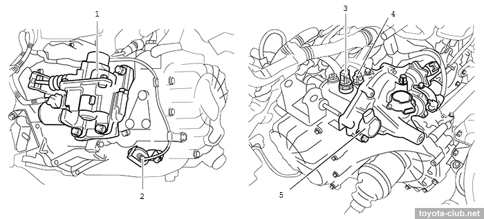
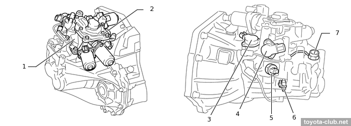
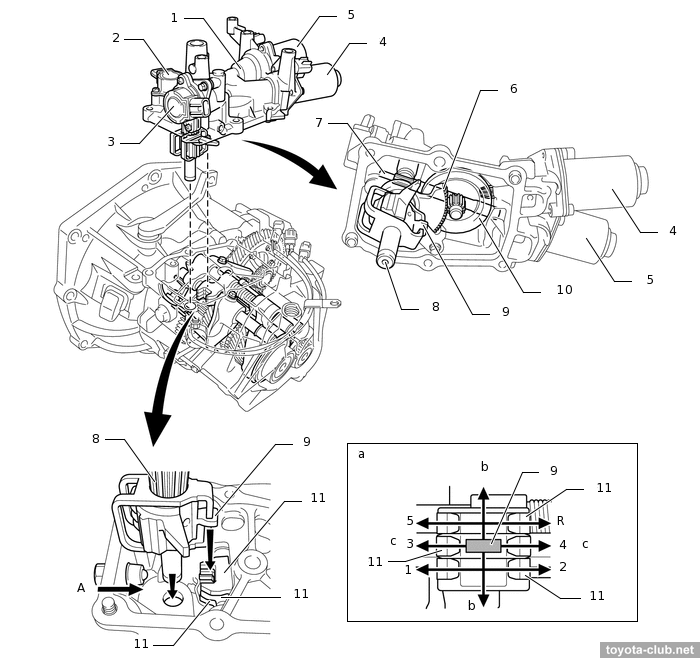
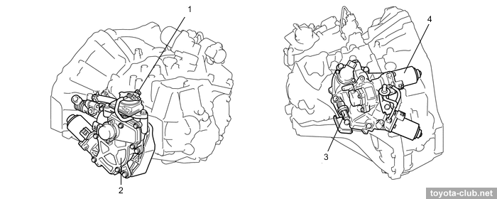
C55#A, C251A, C5#A - created on a basis of the corresponding manual gearboxes, supplemented with select and shift actauators, clutch actuator, as well as speed sensor and PNP sensor.
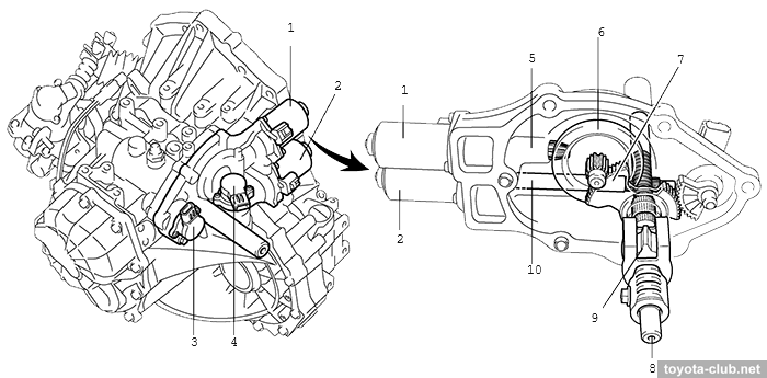
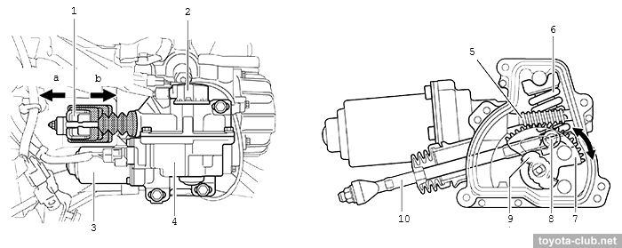
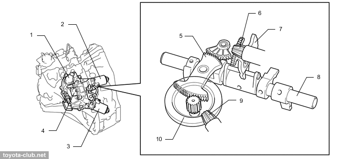
Shift&select actuator (C53A). 1 - shift and select actuator, 2 - shift stroke sensor, 3 - select stroke sensor, 4 - shift motor, 5 - select motor, 6 - rotation lever, 7 - select motor shaft, 8 - shift and select lever shaft, 9 - shift and select lever, 10 - ring gear, 11 - shift fork shaft lever. b - select, c - shift
The shift motor via reduction gear rotates and the select motor via gear-rack pair slides the shift and select lever shaft, then the movement is transmitted to the shift fork shaft. The actuator positions are monitored by two Hall-effect stroke sensors.
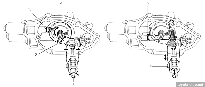
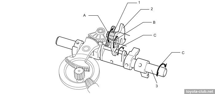
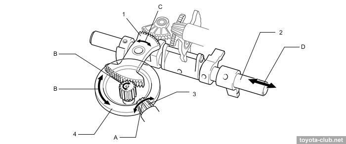
Shift&select actuator (C53A) /operation/. 1 - ring gear, 2 - rotation lever, 3 - shift and select lever shaft, 4 - inner shaft.
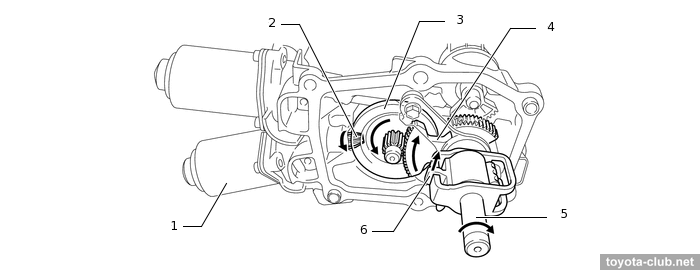
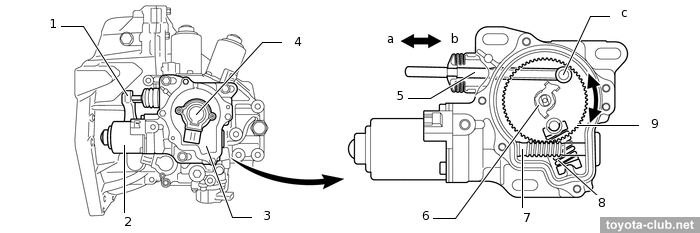
Shift actuator (C553A) /operation/. 1 - shift motor, 2 - shift motor shaft (gear), 3 - ring gear, 4 - rotation lever, 5 - shift and select lever shaft, 6 - shift and select lever
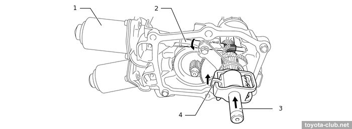
Select actuator (C553A) /operation/. 1 - select motor, 2 - select motor shaft, 3 - shift and select lever shaft, 4 - shift and select lever
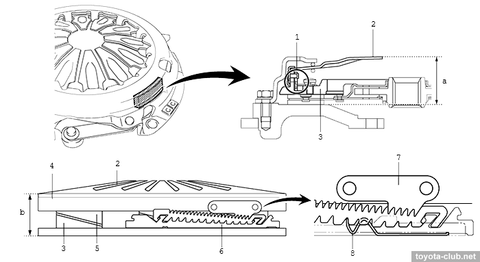
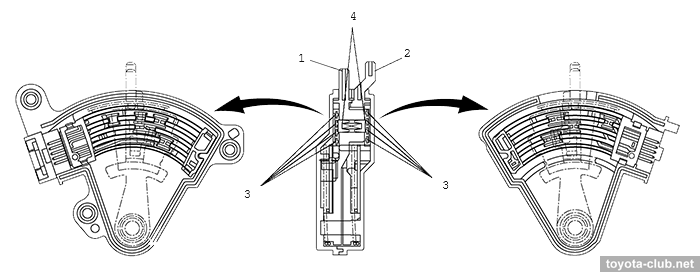
The clutch motor via the worm gear and the fulcrum moves the rod and the clutch release lever. The auxiliary spring provides additional force to move the rod, reducing the load on the actuator when the clutch is disengaged. The position of the actuator is monitored by a Hall-effect stroke sensor.
The clutch cover is equipped with a load controled (LCC) mechanism. If the control unit detects a load increase in the clutch drive as a result of the wear of the clutch disc (measuring current of the actuator motor), then the special mode (with increased clutch stroke) is activated and the LCC mechanism shifts to the next position, changing the height of the pressure plate.
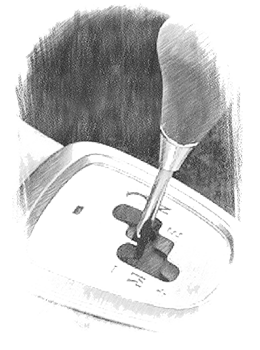
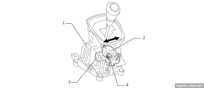
MMT uses a shift-by-wire principle - the selector is not mechanically connected to the gearbox, and its position is monitored by a multi-position contact position sensor. MMT operation modes are: E (normal), Es ("sport"), M (manual shifting). In manual mode, the driver can use the shift paddles under the steering wheel.
Selector (C553A). 1 - shift lock control unit, 2 - shift lever position sensor, 3 - shift lock solenoid, 4 - transmission shift main switch
Selector position sensor (C53A). 1 - link 1, 2 - link 2, 3 - contact point plate, 4 - contact point
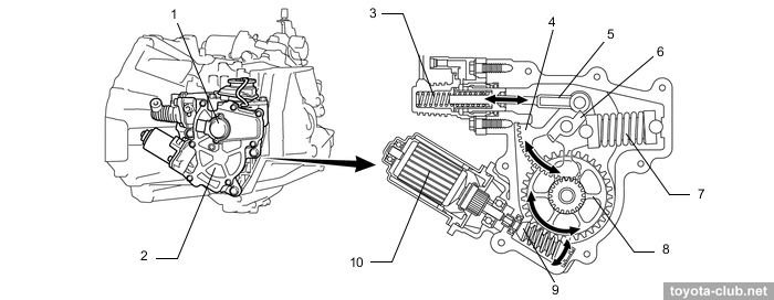
6-speed MMT
Later robots EC6#A differed from the 5-MMT in the kinematics of the select and shift actuators, presence of a hydraulic clutch drive and absence of LLC.
When the select motor is running, rotation is transferred to the pinion gear (A), which moves the plate (B) and than activates the shift and select lever (C).
Select actuator (EC60A) /operation/. 1 - select pinion gear, 2 - select actuator plate, 3 - shift and select lever
When the shift motor is running, rotation is transmitted to the pinion gear (A), then to the driven gear and the gear mounted on it (B). This moves the shift actuator plate (C) and activates the shift and select lever (D).
As a result, the shift fork shaft lever moves and gears are changing.
When the clutch motor is runnung, the torque is converted by a worm gear, and the rotation is transformed into a movement of the rod. The rod pressurizes the clutch master cylinder allows to engage and disengage the clutch. The auxiliary spring reduces the load on the actuator when the clutch is disengaged, providing additional force on the rod.
Open or short in speed sensor circuit
Speed sensor
Combination meter
Transmission control ECU
Skid control ECU
The transmission control ECU detects the following conditions simultaneously:
(a) Vehicle is being driven: Transmission revolution sensor signal is less than 1650 rpm
(b) Vehicle speed signal is more than 9 km/h
(c) Gear is engaged
(d) 4 seconds or more
P0562
96
System voltage
Open in power source circuit
Transmission control ECU
+B terminal input voltage is 7.0 V or less for 0.5 seconds or more
P0603
98
Internal Control Module Keep Alive Memory (KAM) Error
Transmission control ECU
Check errors
P0613
99
TCM processor
Transmission control ECU
CPU communication malfunction
P0617
-
Starter relay circuit high
Neutral position switch
ST (Starter) relay
Wire harness or connector
Ignition switch
TCM
ECM
Following conditions (1), (2) and (3) met for 20 seconds (1-trip detection logic):
Vehicle speed is 20 km/h or more.
Engine speed is more than 1000 rpm.
STA signal is ON
P0703
95
Brake switch B circuit
ECU–IG fuse
STOP fuse
Stop lamp switch
Open in STP or ST1– signal circuit
Transmission control ECU
Conditions (a), (b) and (c) are detected simultaneously for 1.0 second or more
(a) Ignition switch ON
(b) STP signal OFF
(c) ST1– signal OFF
P0715
19
Input/turbine speed sensor circuit
Open or short in transmission revolution sensor circuit
Transmission revolution sensor
Transmission control ECU
The transmission control ECU detects the following conditions simultaneously:
(a) Vehicle speed is 11 km/h or more
(b) Transmission revolution speed is 175 rpm or less for 4 sec.
P0725
13
Engine speed input circuit
Crankshaft position sensor
Open or short in NE circuit
Transmission control ECU
• When the following condition lasts for a certain period, the
transmission control ECU detects this DTC.
The engine speed signal which is sent to the transmission
control ECU from the ECM by the CAN communication differs
from the engine speed signal from terminal NEO of the ECM.
• The transmission control ECU detects the following conditions simultaneously:
(a) Engine speed is 400 rpm or less (NEO circuit)
(b) Engine speed is 400 rpm or more (CAN circuit)
(c) The engine speed difference between (a) and (b) is 400 rpm or more for 1.0 sec
P0806
29
Clutch position sensor circuit (range/performance)
Clutch stroke sensor
Open or short in clutch stroke sensor circuit
Transmission control ECU
Deviation between sensor signal 1 (main) and sensor signal 2 (sub) is 2.0 mm or more for 1.0 sec. or more.
P0807
25
Clutch position sensor circuit (low)
Clutch stroke sensor
Open or short in clutch stroke sensor circuit
Transmission control ECU
Clutch stroke sensor (main) voltage is 0.2 V or less for 0.5 sec. or more.
P0807
27
Clutch position sensor circuit (low)
Clutch stroke sensor
Open or short in clutch stroke sensor circuit
Transmission control ECU
Clutch stroke sensor (sub) voltage is 0.2 V or less for 0.5 sec. or more.
P0808
26
Clutch position sensor circuit (high)
Clutch stroke sensor
Open or short in clutch stroke sensor circuit
Transmission control ECU
Clutch stroke sensor (main) voltage is 4.8 V or more for 0.5 sec. or more
P0808
28
Clutch position sensor circuit (high)
Clutch stroke sensor
Open or short in clutch stroke sensor circuit
Transmission control ECU
Clutch stroke sensor (sub) voltage is 4.8 V or more for 0.5 sec. or more.
P0810
35
Clutch position control error
Clutch stroke sensor
Clutch actuator assy (Clutch motor)
Open or short in clutch stroke sensor circuit
Open or short in clutch motor circuit
Clutch disc (Clutch disc cover)
Clutch release fork
Clutch release fork lever
Clutch release bearing
Transmission control ECU
The transmission control ECU detects the following conditions simultaneously:
(a) Clutch motor current is 22 A or more for 2.0 sec.
(b) The difference between the target clutch position and the actual clutch position is 0.3 mm or more.
(c) The amount of clutch stroke movement is 122 mm/sec. or less.
P0812
67
Reverse input circuit (open)
Shift stroke sensor
Select stroke sensor
Back up lamp switch
Open in back up lamp switch circuit
Transmission control ECU
• When the following condition lasts for a certain period, the
transmission control ECU detects these DTCs.
The gear position that the transmission control ECU detects from the shift sensor and the select sensor differs from the signal from the back up lamp switch.
• The transmission control ECU detects the following conditions:
(a) (1) Shift and select stroke sensors send R position signal to transmission control ECU.
(2) Back up lamp switch is OFF for 0.5 seconds.
(b) (1) Shift and select stroke sensors send non–R position signal to transmission control ECU.
(2) Back up lamp switch is ON for 0.5 seconds.
P0812
68
Reverse input circuit (open)
Shift stroke sensor
Select stroke sensor
Back up lamp switch
Open in back up lamp switch circuit
Transmission control ECU
• When the following condition lasts for a certain period, the transmission control ECU detects these DTCs.
The gear position that the transmission control ECU detects from the shift sensor and the select sensor differs from the signal from the back up lamp switch.
• The transmission control ECU detects the following conditions:
(a) (1) Shift and select stroke sensors send R position signal to transmission control ECU.
(2) Back up lamp switch is OFF for 0.5 seconds.
(b) (1) Shift and select stroke sensors send non–R position signal to transmission control ECU.
(2) Back up lamp switch is ON for 0.5 seconds.
P0820
71
Gear lever X–Y position sensor circuit
Shift lever position sensor
Open in shift lever position signal circuit
Transmission control ECU
The transmission control ECU detects the following condition (a), (b) or (c).
(a) Both the LSWN signal and the LSNC signal are OFF for 5.0 seconds.
(b) Both the LSWN signal and the LSNC signal are ON for 30.0 seconds.
(c) The condition that both the LSWN signal and the LSNC signal are ON is detected 10 times within 15.0 seconds
P0820
72
Gear lever X–Y position sensor circuit
Shift lever position sensor
Open in shift lever position signal circuit
Transmission control ECU
The transmission control ECU detects the following condition (a), (b) or (c).
(a) Both the LSWS signal and the LSSC signal are OFF for 5.0 seconds.
(b) Both the LSWS signal and the LSSC signal are ON for 30.0 seconds.
(c) The condition that both the LSWS signal and the LSSC signal are ON is detected 10 times within 15.0 seconds
P0820
73
Gear lever X–Y position sensor circuit
Shift lever position sensor
Open in shift lever position signal circuit
Transmission control ECU
The transmission control ECU detects the following condition (a), (b) or (c).
(a) Both the LSWR signal and the LSRC signal are OFF for 5.0 seconds.
(b) Both the LSWR signal and the LSRC signal are ON for 30.0 seconds.
(c) The condition that both the LSWR signal and the LSRC signal are ON is detected 10 times within 15.0 seconds.
P0820
74
Gear lever X–Y position sensor circuit
Shift lever position sensor
Open in shift lever position signal circuit
Transmission control ECU
The transmission control ECU detects the following condition (a), (b) or (c).
(a) Both the LSWN signal and the LSNC signal are OFF for 5.0 seconds.
(b) Both the LSWN signal and the LSNC signal are ON for 30.0 seconds.
(c) The condition that both the LSWN signal and the LSNC signal are ON is detected 10 times within 15.0 seconds
P0820
75
Gear lever X–Y position sensor circuit
Shift lever position sensor
Open in shift lever position signal circuit
Transmission control ECU
The transmission control ECU detects the following condition (a), (b) or (c).
(a) Both the LSWS signal and the LSSC signal are OFF for 5.0 seconds.
(b) Both the LSWS signal and the LSSC signal are ON for 30.0 seconds.
(c) The condition that both the LSWS signal and the LSSC signal are ON is detected 10 times within 15.0 seconds
P0820
76
Gear lever X–Y position sensor circuit
Shift lever position sensor
Open in shift lever position signal circuit
Transmission control ECU
The transmission control ECU detects the following condition (a), (b) or (c).
(a) Both the LSWR signal and the LSRC signal are OFF for 5.0 seconds.
(b) Both the LSWR signal and the LSRC signal are ON for 30.0 seconds.
(c) The condition that both the LSWR signal and the LSRC signal are ON is detected 10 times within 15.0 seconds.
P0820
77
Gear lever X–Y position sensor circuit
Shift lever position sensor
Open in shift lever position signal circuit
Transmission control ECU
The transmission control ECU detects the following conditions simultaneously.
(a) Shift lever position is N or R
(b) LSW+ signal or LSW– signal is ON for 1.0 second
P0821
79
Gear lever X position circuit
Transmission shift main switch (Built into shift lever assy)
Short in MDSW signal circuit
Transmission control ECU
The transmission control ECU detects the following conditions simultaneously:
(a) Shift lever position is N or R.
(b) MDSW signal is ON for 1.0 second
P0885
17
TCM power relay control circuit (open)
AMT fuse
AMT relay
Open in MREL signal circuit
Open in PGND signal circuit
Open in +BM signal circuit
Transmission control ECU
The transmission control ECU detects the following conditions simultaneously:
(a) Voltage is supplied to MREL circuit
(b) +BM voltage is 6.29 V or less for 0.5 seconds
P0887
18
TCM power relay control circuit (short)
AMT fuse
AMT relay
Short in MREL signal circuit
Short in PGND signal circuit
Short in +BM signal circuit
Transmission control ECU
The transmission control ECU detects the following conditions simultaneously:
(a) No voltage is supplied to MREL circuit
(b) +BM voltage is 6.29 V or more for 0.1 seconds
P0900
21
Clutch actuator circuit
Clutch actuator assy (Clutch motor)
Open or short in clutch motor circuit
Transmission control ECU
The transmission control ECU detects the following condition (a), (b) or (c).
(a) (1) Clutch motor voltage is 0.5 V or less or 14 V or more for 0.5 seconds.
(2) +BM voltage is 10 V or more.
(b) (1) Voltage is supplied to clutch motor.
(2) Clutch motor current is 5 A or more.
(3) Clutch motor current is 1 A or less.
(4) +BM voltage is 10 V or more.
(c) (1) No voltage is supplied to clutch motor.
(2) Difference of maximum and minimum voltage of clutch motor terminal MCL+ or MCL– is 10 V or more for 0.5 seconds.
P0905
59
Gate select position circuit (range/performance)
Select stroke sensor
Open or short in select stroke sensor circuit
Transmission control ECU
Deviation between sensor signal 1 (main) and sensor signal 2 (sub) is 2.0 mm or more for 1.0 second.
P0906
55
Gate select position circuit (low)
Select stroke sensor
Open or short in select stroke sensor circuit
Transmission control ECU
Select stroke sensor (main) voltage is 0.2 V for 0.5 seconds or more.
P0906
57
Gate select position circuit (low)
Select stroke sensor
Open or short in select stroke sensor circuit
Transmission control ECU
Select stroke sensor (sub) voltage is 0.2 V for 0.5 seconds or more
P0907
56
Gate select position circuit (high)
Select stroke sensor
Open or short in select stroke sensor circuit
Transmission control ECU
Select stroke sensor (main) voltage is 4.8 V for 0.5 seconds
or more
P0907
58
Gate select position circuit (high)
Select stroke sensor
Open or short in select stroke sensor circuit
Transmission control ECU
Select stroke sensor (sub) voltage is 4.8 V for 0.5 seconds or more
P0909
37
Gate select control error
Select stroke sensor
Shift and select actuator assy (Select motor)
Open or short in select stroke sensor circuit
Open or short in select motor circuit
Shift head
Transmission control ECU
The transmission control ECU detects the following conditions simultaneously:
(a) Select motor current is 20 A or more for 2.0 seconds.
(b) A difference between the target select stroke and the actual select stroke is 0.3 mm or more.
(c) The amount of select stroke movements is 125 mm/sec. or less.
P0910
51
Gate select actuator circuit
Shift and select actuator assy (Select motor)
Open or short in select motor circuit
Transmission control ECU
The transmission control ECU detects the following condition (a), (b) or (c).
(a) (1) Select motor voltage is 0.5 V or less or 14 V or more for 0.5 seconds.
(2) +BM voltage is 10 V or more.
(b) (1) Voltage is supplied to select motor.
(2) Select motor current is 5 A or more.
(3) Select motor current is 1 A or less.
(4) +BM voltage is 10 V or more.
(c) (1) No voltage is supplied to select motor.
(2) Difference of maximum and minimum voltage of select motor terminal MSL+ or MSL– is 10 V or more for 0.5 seconds
P0915
49
Gear shift position circuit (range/performance)
Shift stroke sensor
Open or short in shift stroke sensor circuit
Transmission control ECU
Deviation between sensor signal 1 (main) and sensor signal 2 (sub) is 2.0 mm for 1.0 second or more.
P0916
45
Gear shift position circuit (low)
Shift stroke sensor
Open or short in shift stroke sensor circuit
Transmission control ECU
Shift stroke sensor (main) voltage is 0.2 V for 0.5 seconds or more.
P0916
47
Gear shift position circuit (low)
Shift stroke sensor
Open or short in shift stroke sensor circuit
Transmission control ECU
Shift stroke sensor (sub) voltage is 0.2 V for 0.5 seconds or more
P0917
46
Gear shift position circuit (high)
Shift stroke sensor
Open or short in shift stroke sensor circuit
Transmission control ECU
Shift stroke sensor (main) voltage is 4.8 V for 0.5 seconds or more
P0917
48
Gear shift position circuit (high)
Shift stroke sensor
Open or short in shift stroke sensor circuit
Transmission control ECU
Shift stroke sensor (sub) voltage is 4.8 V for 0.5 seconds or more.
P0919
36
Gear shift position control error
Shift stroke sensor
Shift and select actuator assy (Shift motor)
Open or short in shift stroke sensor circuit
Open or short in shift motor circuit
Synchronizer ring
Shift fork
Hub sleeve
Transmission control ECU
The transmission control ECU detects the following conditions simultaneously:
(a) Shift motor current is 32 A or more for 2.0 seconds.
(b) A difference between the target shift stroke and the actual shift stroke is 0.3 mm or more.
(c) The amount of shift stroke movements is 125 mm/sec. or less
P0920
41
Gear shift forward actuator circuit
Shift and select actuator assy (Shift motor)
Open or short in shift motor circuit
Transmission control ECU
The transmission control ECU detects the following condition (a), (b) or (c).
(a) (1) Shift motor voltage is 0.5 V or less or 14 V or more for 0.5 seconds.
(2) +BM voltage is 10 V or more.
(b) (1) Voltage is supplied to shift motor.
(2) Shift motor current is 5 A or more.
(3) Shift motor current is 1 A or less.
(4) +BM voltage is 10 V or more.
(c) (1) No voltage is supplied to shift motor.
(2) Difference of maximum and minimum voltage of shift motor terminal MSF+ or MSF– is 10 V or more for 0.5 seconds
P1875
22
Buzzer malfunction
Transmission control ECU
The transmission control ECU detects the following conditions simultaneously:
(a) The buzzer does not sound.
(b) Buzzer operation voltage is 3 V or less for 5.0 seconds.
U0001
A2/102
High speed CAN communication bus - Lost Communication with ECM / PCM A
Open or short in CAN signal circuit
ECM
Transmission control ECU
No communication from the ECM
Experience
In 2013, corks and champagne were popping in all dealer service workshop of the country: it was three years since the sale of the last model with a robot, and now their problems ceased to be a warranty case, but, on the contrary, turned into a new way to rob clients.
Who would have thought that completely new and, frankly, primitive Toyotas, with a low milage can cause so much regularly recurring troubles. Some of them were simply dangerous - for example, shift to neutral gear at the most inopportune moment (like overtaking). Some are unpleasant - the disappearance of the creep mode (usually characterized as a lack hill-start assist and car pulling back), plus the usual for robots jerks and inadequacies. AMT did not like a long traffic jams. Did not like too hot weather in summer and too cold temperatures in winter. And of course, the owner should constantly expect of that inevitable moment when the AMT will refuse to engage gears and completely immobilize the car (at best, the first time it will be cured by the ignition switch off-on).
The vast majority of troubles were somehow related with the clutch: wear of the bushings of the actuator worm wheel, overload and burn-off of the actuator motor, wear of the motor brushes, scuffing of the release bearing guide, rapid wear of the clutch disc, overheating, inoperability of the LCC mechanism... Mechanical defects caused a load increase, the motor current exceeded the threshold and the notorious error P0810 was not long in coming. Select/shift actuators were much less capricious, but also not eternal. The selector position sensor suffer aging and oxidative processes. The cherry on top was poor software quality - the final revisions of the control units coding appeared almost in the mid-2010s, after a decade of dubious experiments.
During those 7-8 years, while robots were quite relevant, the owners, through their sad experience and private craftsmen, by trial and error, discovered a lot of subtleties in repair and operation. What, unlike time-tested automatic transxles, MMT work in a delicate balance of elements, which is simple to disrupt and difficult to restore. That it is necessary to monitor changes in production, using latest modifications of spare parts for the repair. That, on the one hand, you will have to abandon experiments with a non-OEM parts, and on the other hand, DIY improvements will become the norm. That the PC-DLC3 diagnostic cable should always be in the glove box, and the techstream label can be attached to the notebook taskbar (MMT live data parameters should have been checked at least as often as the engine oil was changed). That the repair may not give any result if it is performed by usual technician but not specially skilled in Toyota MMT master.
Finally, some overlooked that works with the MMT transmission should be accompanied by one or another component of the whole complex of initializations and calibrations (Target Clutch Clamp Position Control, Clutch Actuator Preload, Initialization of MMT ECU, Initial Calibration of MMT System, MMT Synchronization Position Calibration). Others (including dealers), on the contrary, performed the initializations and reset of adaptations/settings for any reason, without replacing the corresponding components, which only accelerated the malfunction development and the likelihood of breakage of other elements.
Well, practical folk experience found the most radical way to solve the MMT problems - a swap for a traditional hydromechanical automatic transmission, which was available for gasoline models (e.g. U341E) and was cheaper than one high-quality MMT repair.
And as usual, before starting work, it is recommended to look through the genuine bulletins on the topic of interest - for MMT, more than enough of them have been released and revised, below are the most recent and relevant ones.
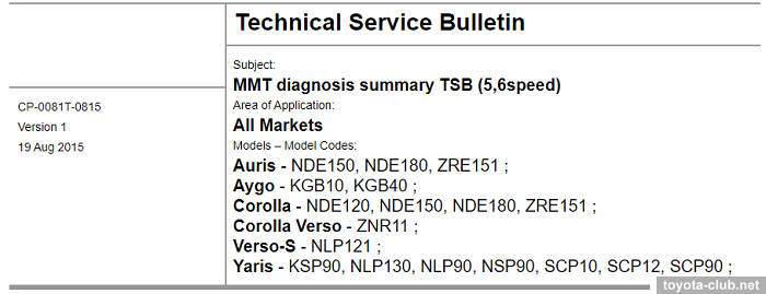
• Today, the first document for any problems with MMT - TSB CP-0081T-0815 "MMT diagnosis summary TSB (5,6speed)" (2015) - describes the primary diagnosis algorithm and specifies the direction of the search, with reference to several options for standard faults and TSBs.
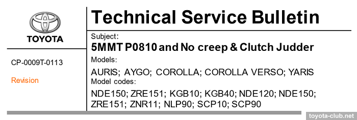
• TSB CP-0009T-0113 "5MMT P0810 and No creep & Clutch Judder" (2015) replaced a number of bulletins of previous decade (CP-0006T-0112, CP-0021T-0110, CP-0026T-0110, CP-0071T-1208, CP-5013, CP-6003...). The changes affected the software of the control unit, the friction in the clutch release mechanism was reduced, the torque of the clutch motor increased.
The document prescribes the installation of a modified MMT control unit (89530-12251 ⇒ 04009-31112)*, clutch kit (31250-19095 ⇒ 04000-03352)*, clutch actuator kit (04008-39112 ⇒ 04000-19112, includes release bearing and fork)*.
* - example shows Auris ZRE151 part numbers
Some other TSB:
CP-0011T-0212 "6MMT DTC P0920" (2012, shiftselect actuator replacement)
CP-0018T-0110 "DTC P0905 P0915 on C53A transmissions (MMT)" (2010, engine compartment wiring replacement)
CP-0022T-0411 "6MMT DTC P0900 Clutch actuator circuit" (2014, actuator motor circuit short due to contamination of brushes wear particles)
CP-0037T-0412 "6MMT Engine does not crank - Neutral start switch" (2012, PNP replacement)
CP-0085T-1213 "Aygo 5speed MMT impossible to drive due to release bearing breakage" (2015, clutch kit, fork and release bearing replacement)
CP-0116T-1010 "6-MMT malfunction resulting in DTC P0810" (2010, clutch stroke sensor and clutch disk replacement)
CP-0149T-1214 "6 speed MMT malfunction resulting in DTC" (2014, clutch stroke sensor, clutch disk and clutch actuator replacement)
As a result, we can say that MMTs are confidently included in the top technological failures of Toyota's recent history. And the best solution to their problems is still prevention - it is enough just not to purchase models with such a transmission.