(FR-based vehicles)
|
Eugenio,77
Fulltime all-wheel drive with a viscous coupling in the center differential used for AT/MT FR-based models since 1990: HiAce/RegiusAce 100..200, Regius/Touring HiAce/Granvia/Grand HiAce, Estima 20, LiteAce/TownAce Noah 60/85.
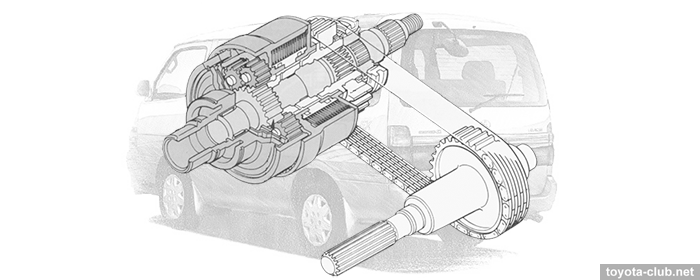
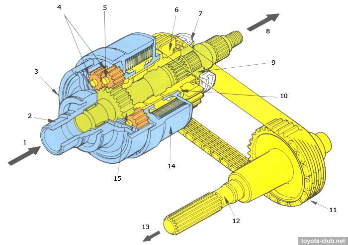
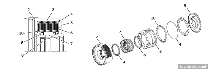
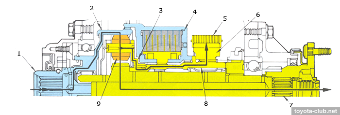
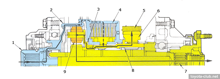
Construction The center differential is a planetary gear type, symmetrical (front-rear torque distribution ratio - 50:50). The transfer input shaft is splined to a planetary ring gear. The viscous coupling housing is splined to the rear end of the planetary ring gear. Six paired planetary pinion gears are used for the center differential: the outer gear is meshed with the planetary ring gear, the inner gear is meshed with the rear output shaft (sun gear). The pinion gear shafts are attached to the planetary carrier. The sprocket sleeve is splined to the rear of the planetary carrier. The inner shaft of the viscous coupling and front drive sprocket are splined to the sprocket sleeve. The silent chain used to transmit power from the center differential to the front propeller shaft.
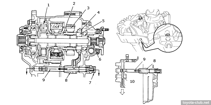
Earlier models with a transfer case TF1AV had a mechanism for selecting a service mode, on later models and models with TF1BV this mechanism was eliminated and all elements were fixed in their normal operating position.
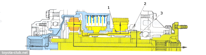
Viscous coupling The coupling controls the operation of the center differential, using the viscous resistance in an organosilicon fluid, which fills about 80% of the free internal volume. The silicone oil has high kinematic viscosity and little change in viscosity with temperature. There is a pack of perforated steel discs inside, alternately connected to splines of the housing or inner shaft. A lot of cuts are made in the discs, creating maximum resistance when mixing the fluid. Spacer rings are inserted between the plates to maintain the necessary clearance. The driving force is transmitted from the transfer input shaft to the housing side via the planetary ring gear, the inner shaft is connected to the planetary carrier via the sprocket sleeve.
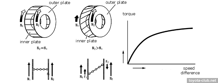
If the outer and inner discs start to rotate at different speeds, then the shear effect occurs (the chains of silicone oil molecules are stretched), creating a resistance force F2 applied to the disc N2 (which rotates faster) in the opposite direction to the rotation. At the same time, a force F1 equal to F2 acts on the disc N1 (which rotates slowly) in the direction of rotation. These forces counteract the difference of discs speed (the amount of viscous friction depends nonlinearly on the speed difference).
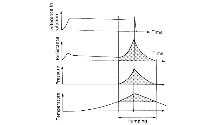
If the discs continue to rotate with a large speed difference intensively mixing the fluid, then the silicon oil temperature rises, oil expands and the pressure inside the coupling increases. The inner discs moved along the splines in the direction where the pressure is less, and are tightly pressed against the outer discs, creating the highest possible rotation resistance - the so-called "humping". Since the speed difference disappears, the temperature and pressure in the coupling gradually decrease, and the compressed air bubbles in the fluid expand, pushing the discs apart - the coupling returns to viscous friction. Under normal conditions, without long-time wheel slipping, the hump effect does not occur.
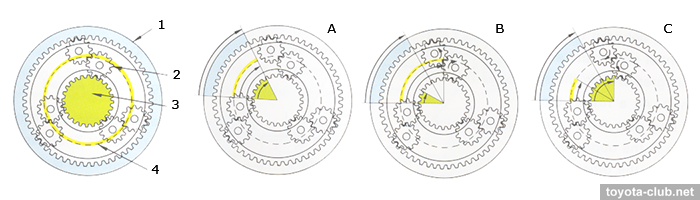
Straight driving While the rolling resistances of the front and rear driving wheels are equal, the pinion gears and sun gear move together in the same direction. The rotational speeds of the planetary carrier and sun gear are the same. The transfer input shaft, drive sprocket and rear output shaft rotate at the same speed. They rotate together with the center differential unit, so the power from the transfer input shaft is distributed equally to the front and rear wheels from the planetary pinion gears. Cornering When the rear wheels roll a shorter distance than the front wheels, and the resistance of the rear wheels becomes greater. The pinion gears rotate around the sun gear when resistance on the rear wheels increases, increasing the speed of the planetary carrier. The resistance on the wheels causes the pinion gears to move around the ring gear and the planetary carrier to rotate around the sun gear, so the sum of the speeds of the planetary carrier and the sun gear becomes double that of the ring gear.
When a speed difference appears between the front and rear wheels, the planetary pinions of the center differential unit rotate and absorb the speed difference. If the speed of the front wheels becomes greater, the drive sprocket rotates faster than the transfer input shaft. The planetary carrier rotates faster, but in the same direction as the planetary ring gear. The outer pinion gears (meshed with the planetary ring gear) to rotate in the opposite direction while orbiting (revolving around) the ring gear in the same direction. So the inner pinion gears rotate in the same direction as the ring gear, the rotation of the rear output shaft becomes slower than the drive sprocket speed by the amount of the pinion gear rotating. When cornering at a low speed, a small rotation difference exists between the front and rear wheels and a small speed difference exists between the outer and inner plates of the viscous coupling, creating a little resistance. The driving force from the transfer input shaft is distributed equally to the front and rear wheels.
Locking If the speed difference between the front and rear wheels becomes great, the viscous coupling works to limit the speed difference of the center differential. When driving on a place with a low coefficient of friction, the front wheels or rear wheels may slip easily, and the center differential prevents the driving force from being transmitted to the wheels that are not slipping. The viscous coupling works to limit the differential, so the driving force is transmitted to the axle that is not idling, and the running performance is improved. If one of the front wheels starts to slip, the drive sprocket rotates faster than the transfer input shaft. The viscous coupling increases the differential limiting torque in proportion to the speed difference, to increase the power is transmitted to the rear wheels - if the speed difference between the front and rear wheels is great, the speed difference between the outer and inner plates of the viscous coupling becomes great, and the viscous resistance is generated, so the power is distributed from the faster side to the slower side.
When the center differential is locked, the lock pin and shaft plug are released and the shaft slides toward the front. So the clutch sleeve and the sprocket sleeve are meshed and the front drive sprocket and rear output shaft turn as unit, and the center differential does not operate.
Toyota all-wheel drive. Review |
|