(FF-based vehicles)
|
Eugenio,77
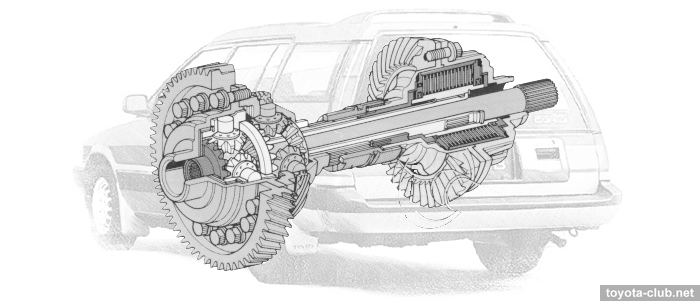
Full-time all-wheel drive with a viscous coupling in the center differential used for MT models in the period of 1987-2005: Corolla/Sprinter 90..100..110, Corona/Carina/Caldina 170..190..210, Carina ED/Corona Exiv 200, Celica 180..200, Vista/Camry 20..30..40, RAV4 20. A similar mech used for AT models in the period of 1997-2013: Alphard 10, Caldina 210..240, Harrier 10..30, Highlander 20, Kluger, Lexus RX, RAV4 20.
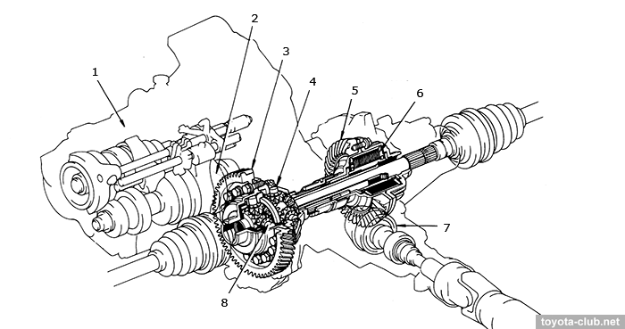
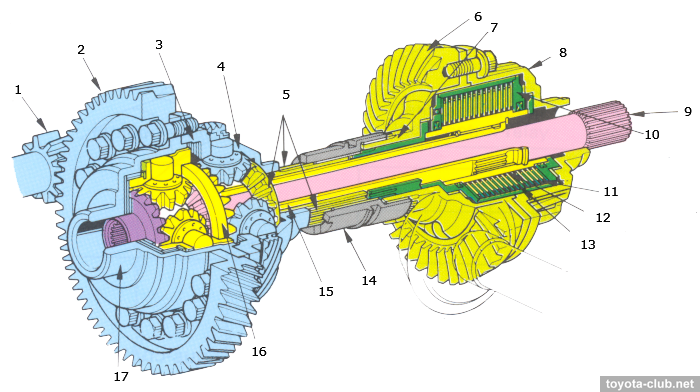
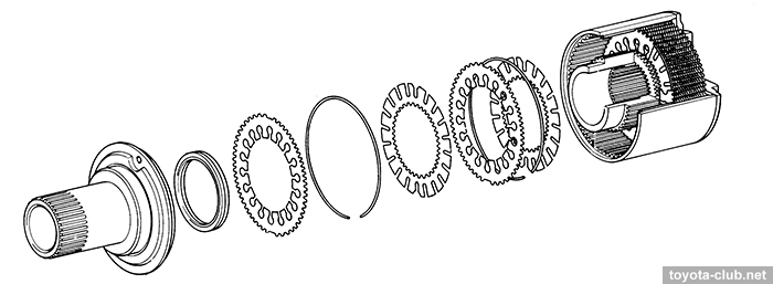
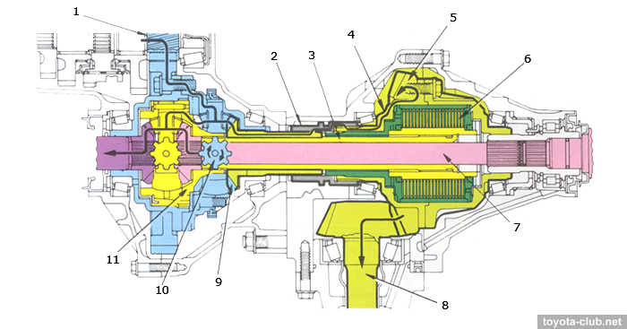
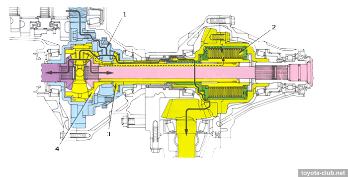
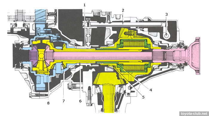
Construction The center differential left and central cases are installed on c.d. ring gear. The front differential is housed in c.d. left case. The c.d. right side gear is integrated with the splined-end hollow shaft. The left end of the transfer drive gear left carrier is integrated with a hollow shaft. The c.d. left side gear is integrated with the f.d. case, the intermediate shaft 2 is inserted into this gear. The right end of the intermediate shaft 2 is splined to the viscous coupling inner shaft. Early models: The right end of c.d. right case is provided with dog clutch teeth for mode selection sleeve. A dog clutch sleeve is installed on the splined portion and can slide along the spline. The left end of the hollow shaft from v.c. housing is splined so that the sleeve can slide along it.
Later models: There is not a service mode selection mechanism, so all the parts are secured at the normal operation position (the transfer drive gear left carrier and mode select sleeve are integrated).
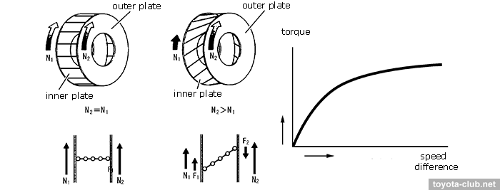
The viscous coupling operates when rotational speed differences occur between its inner and outer plates, transmitting power and limiting the differential action. The inner plates are joined to the front differential, while the outer plates are joined to the transfer drive gear. So, rotational speed differences between the front and rear axles become speed differences in the viscous coupling. Viscous coupling The coupling controls the operation of the center differential, using the viscous resistance in an organosilicon fluid, which fills about 80% of the free internal volume (unlike canonical descriptions, the Toyota documentation emphasizes that the viscosity of this oil is weakly dependent on temperature - it doesn't "hardens from heating"). There is a pack of perforated steel discs inside, alternately connected to splines of the housing or inner shaft. A lot of cuts are made in the discs, creating maximum resistance when mixing the fluid. Spacer rings are inserted between the plates to maintain the necessary clearance.
If the outer and inner discs start to rotate at different speeds, then the shear effect occurs (the chains of silicone oil molecules are stretched), creating a resistance force F2 applied to the disc N2 (which rotates faster) in the opposite direction to the rotation. At the same time, a force F1 equal to F2 acts on the disc N1 (which rotates slowly) in the direction of rotation. These forces counteract the difference of discs speed (the amount of viscous friction depends nonlinearly on the speed difference).
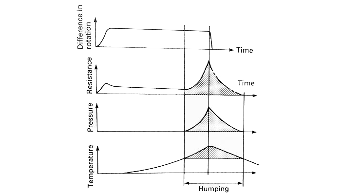
If the discs continue to rotate with a large speed difference intensively mixing the fluid, then the silicon oil temperature rises, oil expands and the pressure inside the coupling increases. The inner discs moved along the splines in the direction where the pressure is less, and are tightly pressed against the outer discs, creating the highest possible rotation resistance - the so-called "humping". Since the speed difference disappears, the temperature and pressure in the clutch gradually decrease, and the compressed air bubbles in the fluid expand, pushing the discs apart - the coupling returns to viscous friction. Under normal conditions, without long-time slipping of the front wheels, the hump effect does not occur.
Straight-driving The power from the c.d. drive gear is transmitted to the c.d. right and left side gears. From the c.d. right side gear it is transmitted via the mode select sleeve to the transfer drive gear, driven gear and propeller shaft, and it is also transmitted to the v.c. outer plate. From the c.d. left side gear the power is transmitted to the right and left f.d. gears via the f.d. case, pinion shafts, and pinion gears. The intermediate shaft 2 is inserted into the c.d. left side gear, so the power is also transmitted to the v.c. inner plate. Cornering While cornering, the turning radii of the front and rear wheels differ. The number of revolutions of the rear wheels is smaller than that of the front wheels, cause a difference of revolutions between the c.d. right and left side gears, that is absorbed by the rotation of the c.d. pinion gears. Since the v.c. acts to reduce the speed difference between the c.d. right and left side gears, the differential action is limited, but the limiting force is not so strong and allows smooth turning.
Viscous coupling operation The vicsous coupling suppresses operation of c.d. and increases the power transmitted to the non-slipping wheels. If the front wheels tend to be turned faster than the rear wheels, the c.d. left side gear tends to turn faster than the right side gear. The faster the left side gear turns, the more resistance is created by v.c. to prevents left side gear from turning smoothly, and the rotational speed of the right side gear increases proportionally. The power transmission to the front wheels decreases, and more power is transmitted to the rear wheels.
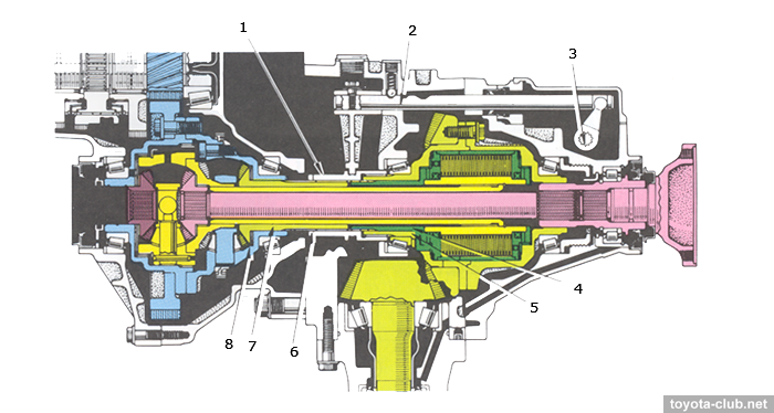
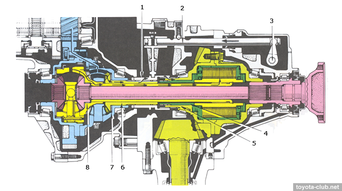
Mode selection sleeve
The mode select sleeve has splines inside and slides along to allow or stop the transmission of power from the c.d. right side gear to the transfer drive gear carrier and v.c. housing. A "dog clutch" is integrated with the left end of the sleeve to mesh with the c.d. case. When the mode select lever on the transfer case turns, the shift fork shaft and the shift fork also move and force the sleeve to slide in an axial direction.
(2) "FREE" mode. The shaft and the shift fork slide to the left, moving the sleeve to the left. The sleeve is disengaged from v.c. housing. Power not transmitted from c.d. right side gear to v.c. and v.c. rotates constantly at the same speed as c.d. left side gear. The sleeve is engaged with the transfer drive gear carrier via splines, so the power is transmitted by the sleeve from c.d. right side gear to the propeller shaft via the transfer, as in the free-type c.d.
(3) "2WD" mode. The shaft and the shift fork slide far to the left, moving the sleeve further to the left. The sleeve is already disengaged from v,c, housing, and it also becomes disengaged from the transfer drive gear carrier. So, power is not transmitted from c.d. right side gear to the transfer drive gear carrier and to the rear wheels. The dog clutch at the left end of the sleeve is meshed with the dog clutch fitted at the right end of c.d. case, so the case is integrated with c.d. right side gear. C.d. is locked and power is transmitted to the f.d. only.
Toyota all-wheel drive. Review |
|