|
Eugenio,77
mail@toyota-club.net
© Toyota-Club.Net
Jan 2016
• Toyota Variable Valve Timing. Evolution
Type VVT-iE - timing drive by chain, electrical variable valve timing mechanism for intake and traditional hydraulic VVT for exhaust. Applied for engines: UR series (1UR-FSE, 2UR-FSE).
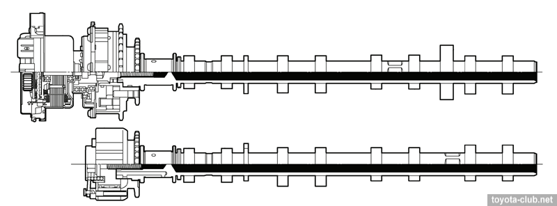
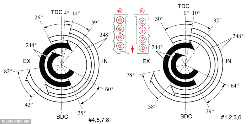
VVT-iE system (Variable Valve Timing - intelligent Electric) allows to smoothly change the valve timing according to engine operating conditions. This is achieved by rotating the intake camshaft relative to the drive sprocket in the range of 40° (crankshaft rotation angle). The electric motor is used for adjustment, which allows to operate effectively at low temperatures or at low engine speeds with low oil pressure. The drive operates directly from power on moment, so it can provide the most optimal timing at starting.
VVT-i system (Variable Valve Timing - intelligent) allows to smoothly change the valve timing according to engine operating conditions. This is achieved by rotating the exhaust camshaft relative to the drive sprocket in the range of 35° (crankshaft rotation angle).
 |
|
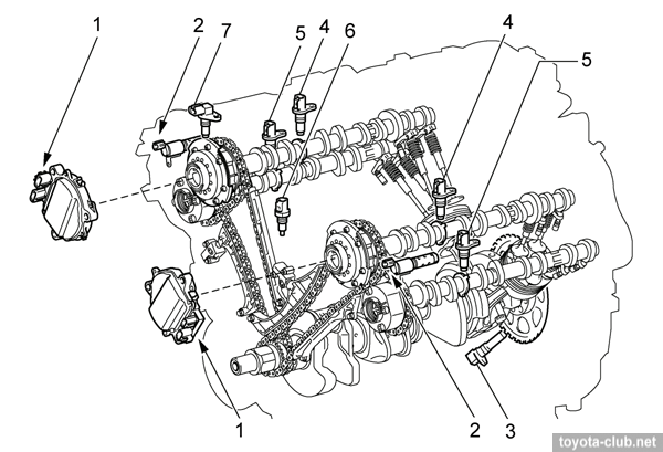
Timing drive (UR series). 1 - VVT-iE motor, 2 - VVT-i control solenoid, 3 - crankshaft position sensor, 4 - camshaft position sensor (intake), 5 - camshaft position sensor (exhaust), 6 - water temperature sensor, 7 - camshaft position sensor.
|
At UR series the main timing chain drives the intake camshaft and than by short connecting chain the exhaust camshaft is driven.
VVT-iE actuator
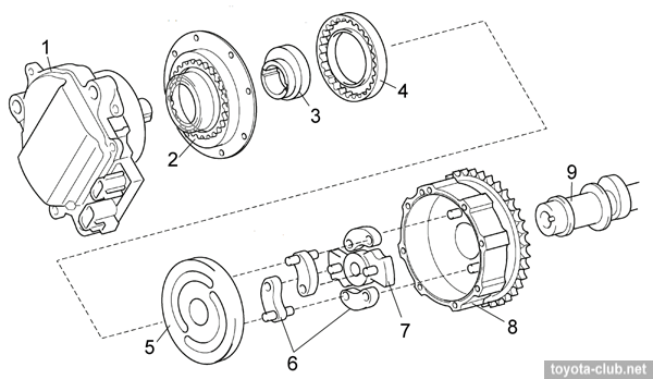
The actuator consists of a lever mechanism and cycloidal reductor.
|
VVT-iE actuator. 1 - motor, 2 - cover (stator gear), 3 - rotor, 4 - driven gear, 5 - spiral plate, 6 - levers, 7 - carrier, 8 - housing (sprocket), 9 - intake camshaft. |
Lever mechanism consists of housing (connected to timing sprocket), carrier (connected to camshaft) and connecting them spiral plate and levers.
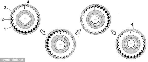
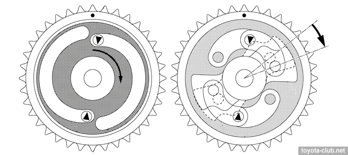
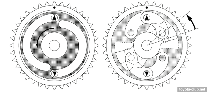
Cycloidal reductor consists of cover (with stator gear), rotor (connected to electric motor) and the driven gear (that having 1 tooth more than the stator gear) connected to the rotor. When motor rotates for 1 turn the driven gear turns in the same direction for 1 tooth.
|
VVT-iE reductor operation. 1 - carrier, 2 - stator, 3 - driven gear, 4 - mark. |
The spiral plate connected to driven gear is driven via reductor. The levers transmit the rotation of the spiral plate to the carrier, rotating camshaft and changing valve timing.
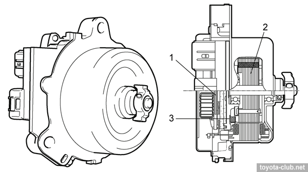
VVT-iE motor consists of brushless DC motor, EDU control unit and Hall sensor. EDU serves as a mediator between ECM and the electric motor, controlling the speed and direction of rotation.
|
VVT-iE motor. 1 - EDU, 2 - electric motor, 3 - Hall sensor. |
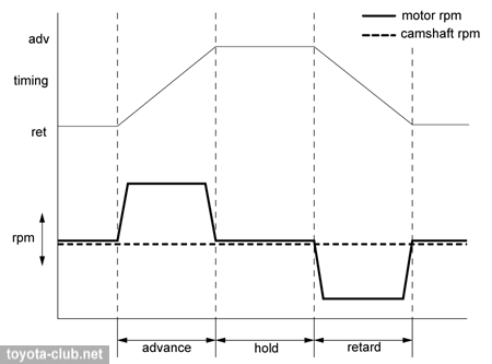
Valve timing adjusting is based on the speed difference between the motor and camshaft. In hold mode the speed is equal. In advance mode the motor rotates faster than camshaft. In retard mode the motor rotates slower than camshaft (or in the opposite direction).
Advance. By ECM signal the motor rotates faster than camshaft. The spiral plate is turned clockwise via the reductor. The levers, inserted into the spiral grooves, are moved to the camshaft center axis and rotate the carrier together with the camshaft in the advance direction.
Retard. By ECM signal the motor rotates lower than camshaft. The spiral plate is turned anticlockwise via the reductor. The levers, inserted into the spiral grooves, are moved from the camshaft center axis and rotate the carrier together with the camshaft in the retard direction.
Hold. After reaching the target timing, motor rotates at the same speed as the camshaft. The lever mechanism is fixed and maintain valve timing.
VVT-i actuator
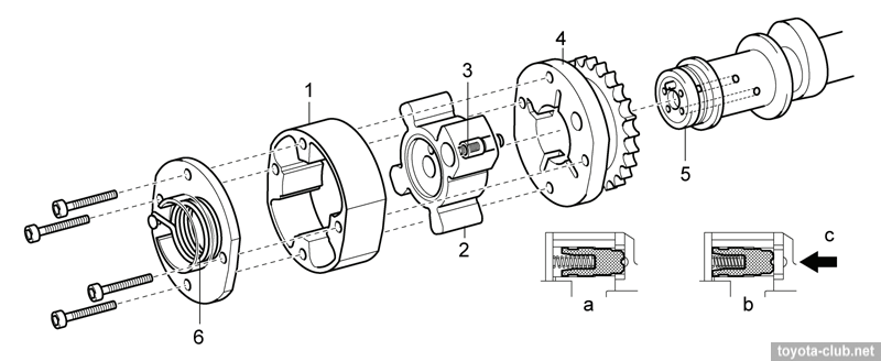
VVT-i actuator with a bladed rotor is installed to the exhaust camshaft. When the engine stopped the lock pin holds the rotor at maximum advance position for normal starting.
Auxiliary spring torque applied in the advance direction to return the rotor and reliable operation of the lock after switching off the engine.
|
VVT-i actuator. 1 - housing, 2 - rotor, 3 - lock pin, 4 - sprocket, 5 - camshaft, 6 - auxiliary spring. a - stop, b - operation, c - oil pressure. |
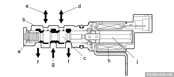
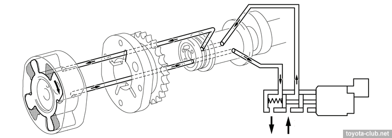
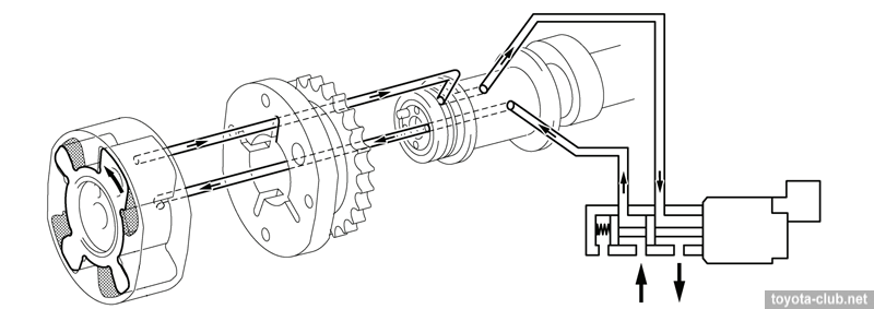
ECM controls the oil flow to advance and retard chambers by solenoid, based on the signals of the camshaft position sensors. When engine stopped the valve spool is moved by spring to ensure maximum advance angle.
|
a - spring, b - sleeve, c - valve spool, d - to actuator (advance chamber), e - to actuator (reatrd chamber), f - drain, g - oil pressure, h - coil, j - plunger. |
Advance. ECM switches solenoid to an advance position and shifts the spool of the control valve. Engine oil under pressure is supplied to the rotor in advance chamber, turning it together with the camshaft in the advance direction.
Retard. ECM switches solenoid to an retard position and shifts the spool of the control valve. Engine oil under pressure is supplied to the rotor in retard chamber, turning it together with the camshaft in the retard direction.
Hold. ECM calculates the target angle according to the driving conditions, and after the set position achieved it switches the control valve to the neutral position until the next change of external conditions, and and retains the oil in the circuit.
Operation modes
| Mode |
# |
Timing |
Condition |
Effect |
| Idling |
1 |
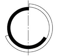 |
Minimal valves overlap. Minimal exhaust gas amount by-pass to intake. |
Stable idle. Reduced fuel consumption. |
| Low to medium load, low rpm |
2 |
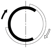 |
Late closing of the intake valves to reduce pumping losses. Increased valves overlap to improve internal EGR. |
Reduced fuel consumption. Reduced emissions. |
| High load, low to medium rpm |
4 |
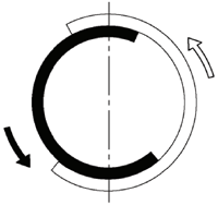 |
Early closing of the intake valve to improve volumetric efficiency and reduce exhaust gas by-pass to intake. |
Increased torque at low and medium rpm. |
| High load, high rpm |
5 |
 |
Late closing of the intake valve to improve volumetric efficiency by inertial charge. |
Increased maximal output. |
| Low temperature |
6 |
 |
Minimal valves overlap. |
Stable idle. Reduced fuel consumption. |
| Starting and stopping |
- |
 |
Optimal valve timing for starting. |
Improved starting conditions. |
Toyota engines review
|
|
|


